Updated - May 2, 2026 - Copyright - Ralph Gibson - 2014

Lathe Projects
Here are some DIY projects for a Wood Lathe, and some turning
examples. The lathe works great for pen turning, but the ~600
RPM minimum speed is a bit fast for applying CA finish. One
lathe upgrade added a stepper motor, allowing the lathe to run
between 0 and 100 RPM. The stepper motor controller is
Arduino based, the speed is set by a single turn potentiometer,
and ramps the spindle speed smoothly up or down.
Please click on an image below for a larger view, or to watch a short video.
Adding a NEMA23 381oz/in Dual Shaft Stepper Motor to the Lathe:
The images below include the following features for the lathe stepper motor upgrade.
1.
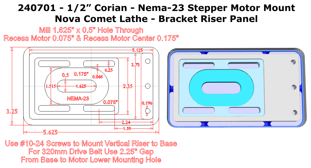
The stepper moter used for the upgrade was the KL23H2100-35-4B
NEMA23 Hybrid Stepper Motor, purchased from Automation Technology,
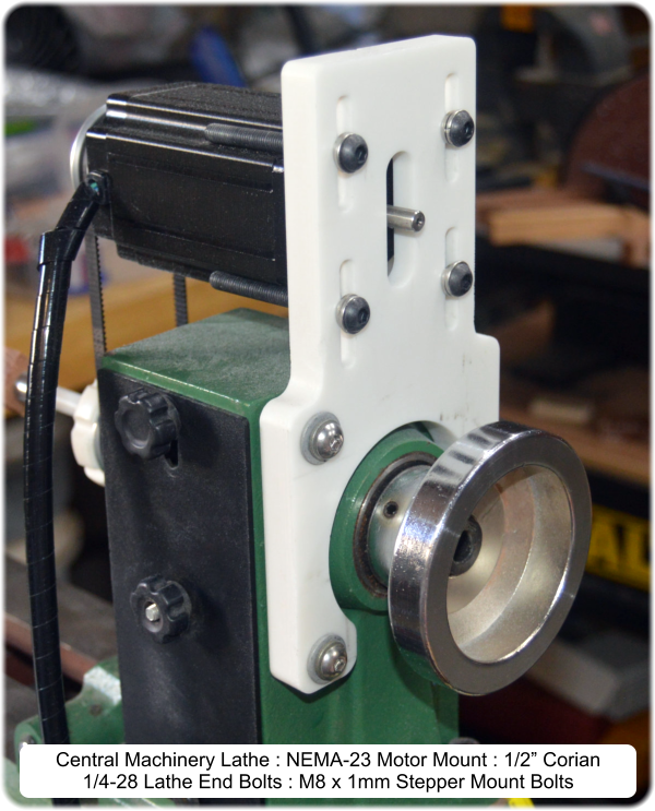
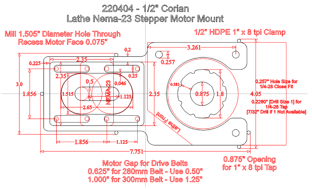
Inc. A motor mount to attach the stepper motor to the lathe was
machined out of 1/2” Corian. For the Central Machinery version, the end
of the lathe was drilled and tapped for three 1/4-28 bolts, to attach the
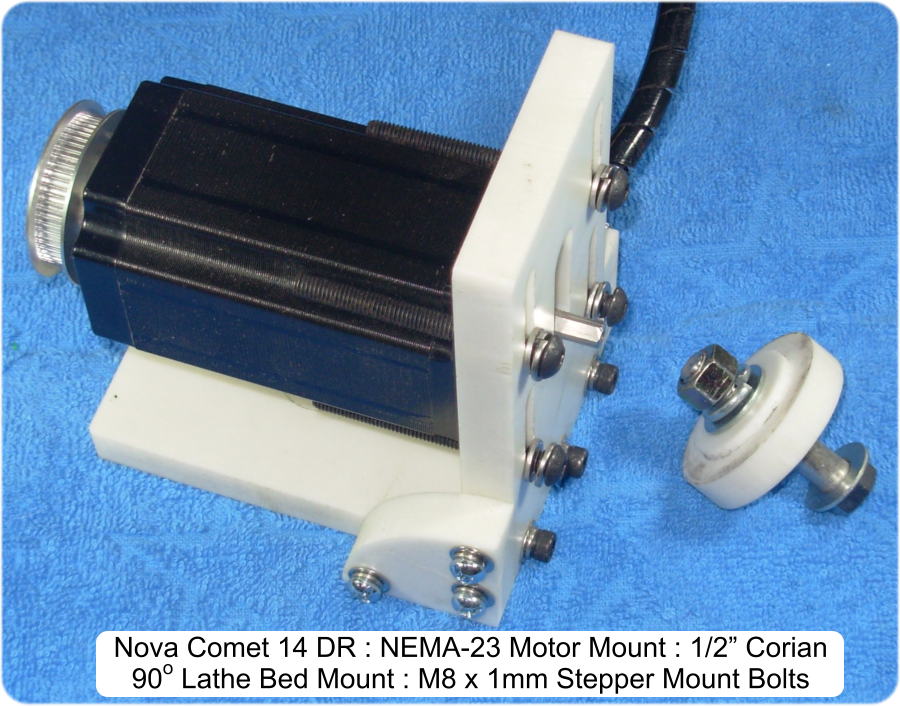
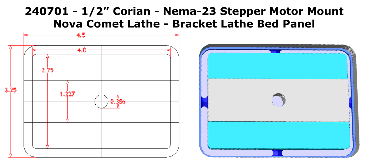
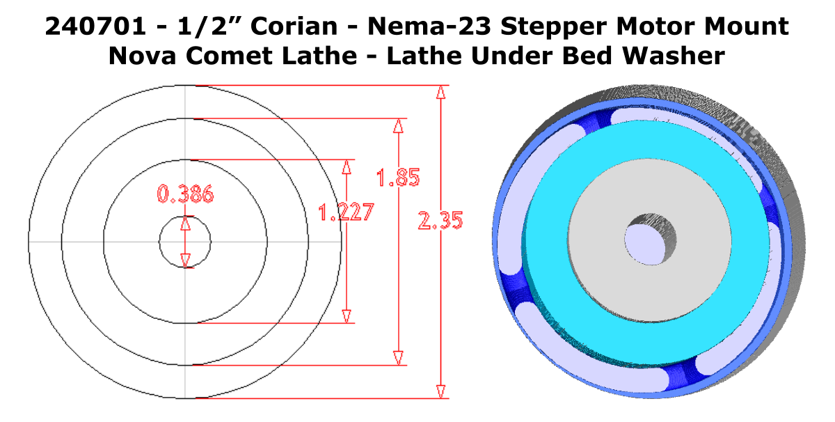
mount to the lathe. For the Nova Comet version, a right angle lathe bed
mount and underside washer was machined. The NEMA23 stepper motor
mounting holes were tapped to allow four M8 x 1mm bolts to support the
stepper motor. Slots were machined into the motor mount, to allow the
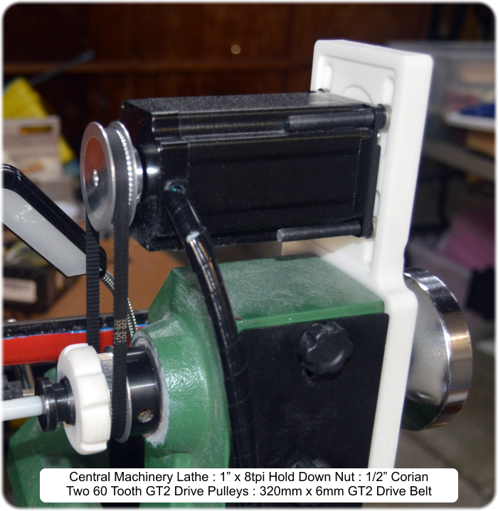
stepper motor to be moved to adjust the tension on the 320mm x 6mm
GT2 timing belt.
2.
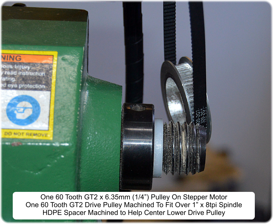
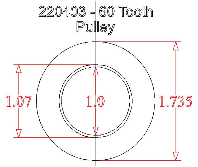
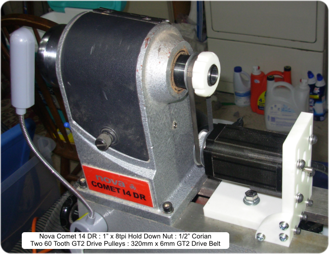
Two 44mm diameter, 60 tooth GT2 timing belt pulleys were used for the lathe spindle drive. The
lower pulley center was machined out to allow it to slip over the 1” x 8tpi lathe spindle. A pulley hold
down nut was machined out of 1/2” Corian, and tapped to fit the lathe spindle threads. A thin HDPE
spacer was machined to help center the lower drive pulley on the spindle.
3.
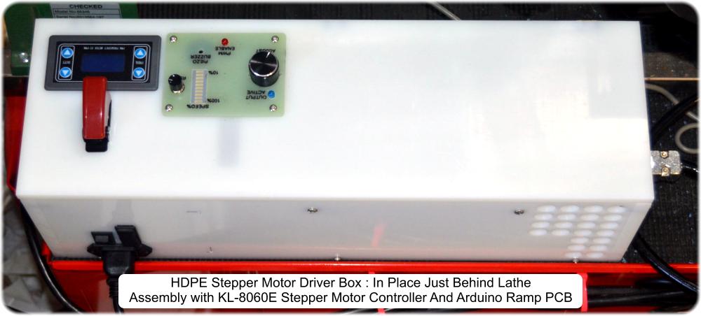
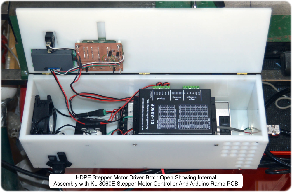
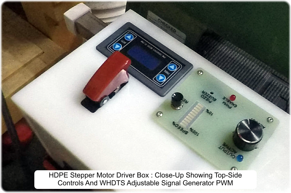
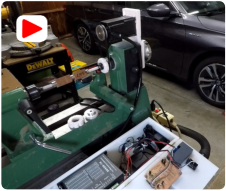
An HDPE box was built to hold the power supplies, KL-8060E stepper motor driver, external WHDTS
PWM generator, and the Arduino-Nano micro-controller smooth ramp clock driver. The Arduino-Nano
board provides a smooth ramp clock up and clock down for the stepper motor KL-8060E driver.
4.
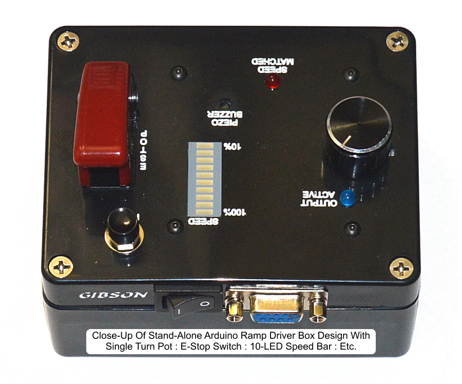
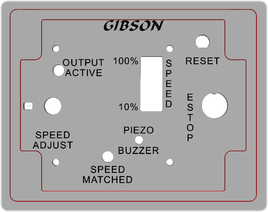
The black box in the photo below, is a stand-alone version of the Arduino-Nano based smooth ramp
generator. The box design includes a DB-9 interface connector for power and control signals, an
Arduino-Nano reset push button switch, and an E-Stop switch. The design also includes a piezo
beeper, a single-turn potentiometer to set the speed, a 10-LED bar to indicated the set speed, and
two LEDS. A blue LED to show when the output clock is being driven, and a red LED to indicate that
the current speed matches the set speed.
5.
The design file clip below will bring up a .PDF file for the Arduino ramp generator design. This
includes a schematic of the design, a bill of materials, images of the printed circuit board, etc.
CNC Milling Files Created with VCarve-Pro Version 10.5:
(Central_Machinery_Milling_Files_220905.zip) & (Nova_Comet_Milling_Files_250218.zip)
Included above is a link to the .zip archive holding the CNC milling files created with VCarve-Pro V10.5.
The images below are screen clips from the VCarve-Pro milling files for the various upgrade components.
Included are the dimension drawings and the CNC milling simulations for each part created. These
include the lathe to stepper motor mount, the GT2 spindle pulley hold down nut, the machining file for the
spindle GT2 pulley, the HDPE GT2 pulley shim, and the stand-alone controller box files.
1.
The stepper motor mount was machined out of 1/2” Corian, and the lower pulley hold down nut is
machined with the mount. After milling, the nut is tapped to fit the 1” x 8tpi lathe spindle threads.
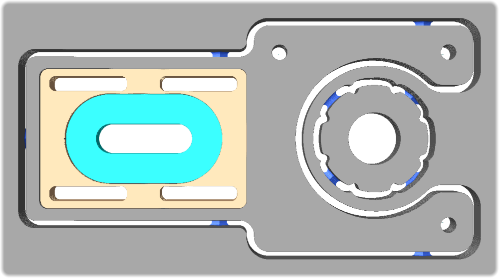
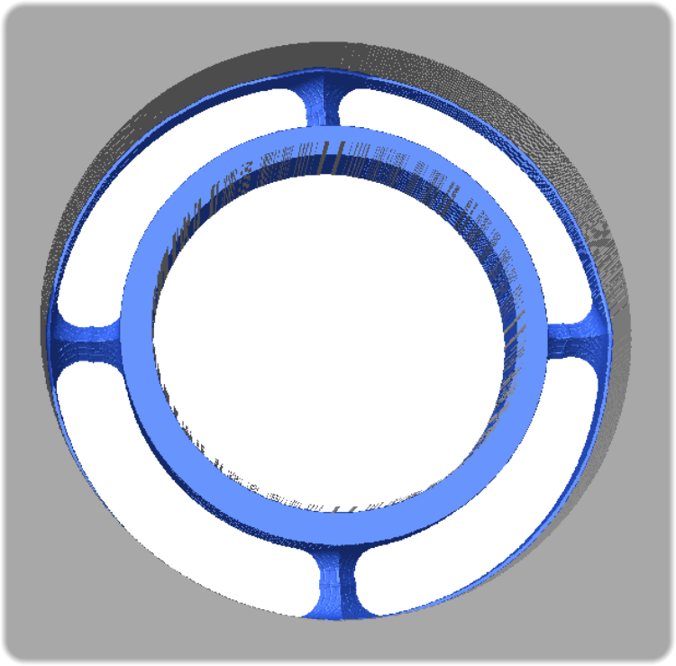
2.
In order to accurately mill the GT2 pulley for the lathe spindle, a recess slightly larger than the pulley
diameter is milled first. The pulley is then clamped into the recess and the center milled out.
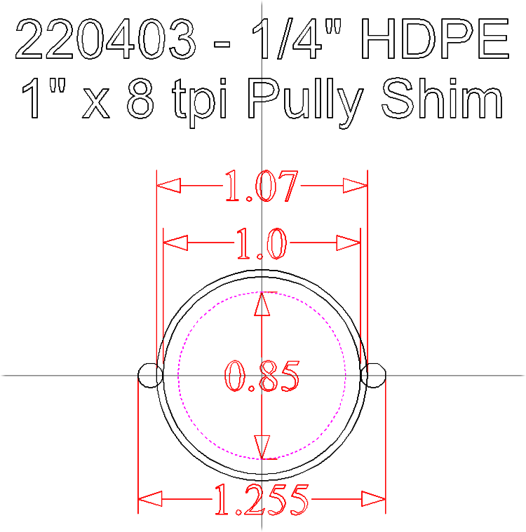
3.
Where the spindle pulley mounts on the lathe, the shaft diameter is slightly less than the 1” diameter
of the threaded portion. The small shim was milled out of 1/4” HDPE, to help center the pulley on
the shaft. The pulley is sliced to create a split shim, which allows it to mount on the lathe shaft.
4.
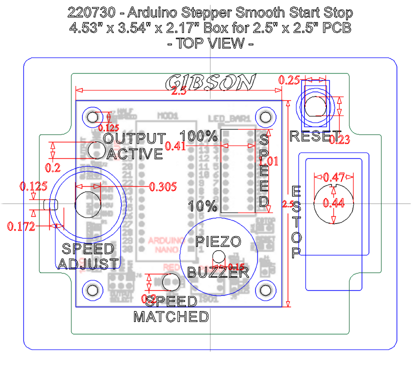
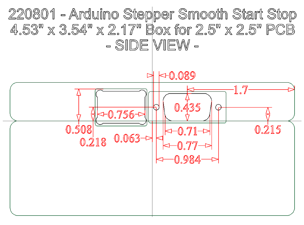
The stand-alone Arduino ramp controller, was built into a small 4.53” x 3.54” x 2.17” two part box
purchased at Amazon. The box design was set up so only the top of the box needs to be milled to
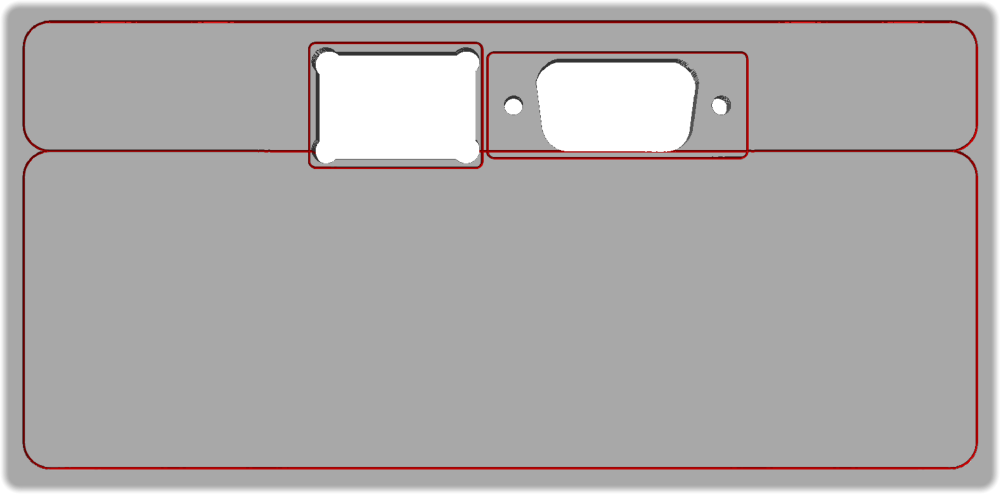
mount the various parts. The back of the lid was milled for an SPST power switch, and a DB9 Female
connector. The nine pin connector brings +5VDC, ground, and an optional PWM signal in, and
outputs OUT_HIGH and OUT_LOW digital signals to drive a stepper motor driver module clock input.
Arduino-Nano Sketch File for Smooth Ramp Generator (Arduino-Nano_Sketch_File_220905.zip):
Included above is a link to the .zip archive holding the Arduino-Nano sketch file used in the design.
Anyone reviewing the Sketch file that I created for the Arduino-Nano will quickly see that I’m not a
programmer. My background is in hardware design and development. However, both of my sons recently
graduated from UCSC with Computer Science as their majors. So with some pointers from them, I was
able to at least create a sketch that works, though I suspect it isn’t very clean or elegant. On power up
or reset, the blue LED and Piezo Beeper run beep code pulses to show the version and revision.
This version will display an E-Stop Fault if the E-Stop switch is in the RUN position at power on or reset.
The fault is indicated by blinking the bottom LED of the 10-LED BAR display. To clear the fault the E-Stop
switch needs to be switched to the STOP position, and then back to run.
EAGLE V5.11 PCB Layout and Gerber Files (Arduino_Ramp_Card_PCB_Layout_220905.zip):
Included above is a link to the .zip archive holding the EAGLE V5.11 PCB layout design and gerber files
used in the design. The .GWK file, is a gerber review file created in GC-Preview V29.2.8.
The 2-layer printed circuit board used for this application was created using EAGLE version 5.11. The
board is 2.5” x 2.5” x 0.0625” and includes components on both sides of the board. All of the surface
mount parts and the 0.1” pin pitch headers are mounted on the bottom side. The other components are
mounted on the board top side.